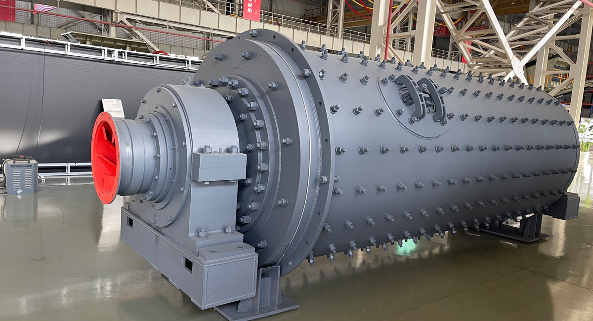
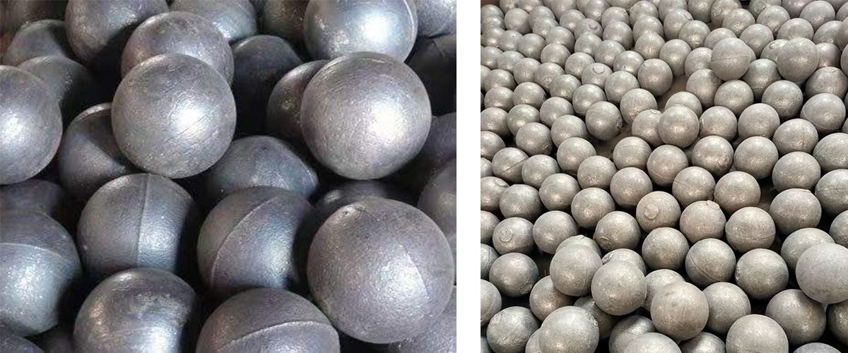
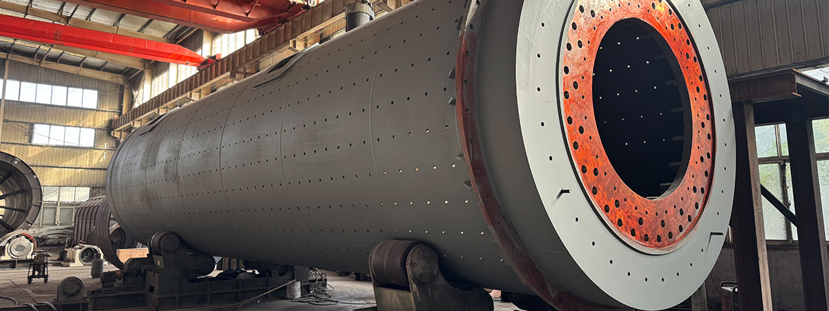
Ball Mill Equipment Overview
• Ball Loading Range: 1.5–338 tons
• Output Range: 0.65–615 t/h
• Applicable Materials: Cement, lime, slag, steel slag, silicate products, glass ceramics, and other mineral materials.
Features and Applications
The ball mill is a key piece of equipment used for grinding materials after they have been crushed. It offers high working efficiency, smooth discharge, and low energy consumption. Ball mills are available in both dry and wet grinding modes.

Application Fields
The ball mill is widely used in the following industries:
• Cement and silicate product production
• New building materials and refractory materials
• Fertilizer production
• Ferrous and non-ferrous metal beneficiation
• Glass and ceramics manufacturing
This equipment is capable of dry or wet grinding of various ores and other grindable materials, providing efficient support for production processes.
Product Functions and Performance Advantages
Structural Features
Main Components:
• Feeding section, discharging section, rotating section
• Transmission section (including reducer, small transmission gear, motor, and electrical control system)
Materials and Design:
• The hollow shaft is made of cast steel, ensuring durability and replaceability.
• The cylinder is lined with wear-resistant liners for extended service life.
• The large rotary gear is precision-manufactured using castings and hobbing technology.

Performance Advantages
1. High-Efficiency Spindle:
• Equipped with large-diameter double-row spherical roller bearings, reducing friction, lowering energy consumption, and increasing throughput.
2. Stable Operation:
• Simple and stable design of combined feeders (union feeder and drum feeder), ensuring smooth operation without inertia impact, effectively minimizing downtime.
3. High-Strength Gears:
• Adopts modified gear design to eliminate undercutting, enhancing the bending strength of gear teeth and improving durability.
4. Extended Bearing Life:
• Enlarged hollow shaft diameter provides better radial clearance between bearings and the spiral tube, delivering improved heat insulation and cooling effects, thereby extending bearing life.
5. Wear-Resistant Components:
• Utilizes high-strength wear-resistant composite hammers to enhance impact resistance, reduce material waste, and increase safety and durability.

Working Principle
The ball mill operates as a horizontal cylindrical rotary device with peripheral gear transmission and two-chamber grate design.
1. Feeding: Materials are evenly fed into the first chamber through the hollow shaft feeding device.
2. Coarse Grinding: The first chamber contains stepped or corrugated liners and steel balls, which perform impact and grinding actions to achieve coarse grinding.
3. Fine Grinding: Materials pass through a single-layer partition board into the second chamber, which contains flat liners and steel balls for further grinding.
4. Discharge: Ground powder is discharged through a grate plate, completing the grinding process.
Technical Data
| Model | Drum Speed (r/min) | Ball Load (t) | Feed Size (mm) | Discharge Size (mm) | Capacity (t/h) | Motor Power (kw) | Machine Weight (T) |
|---|---|---|---|---|---|---|---|
| Ø900×1800 | 38 | 1.5 | ≤20 | 0.075-0.89 | 0.65-2 | 18.5 | 3.6 |
| Ø900×3000 | 38 | 2.7 | ≤20 | 0.075-0.89 | 1.1-3.5 | 22 | 4.6 |
| Ø1200×2400 | 32 | 3.8 | ≤25 | 0.075-0.6 | 1.5-4.8 | 45 | 12.5 |
| Ø1200×3000 | 32 | 5 | ≤25 | 0.074-0.4 | 1.6-5 | 45 | 12.8 |
| Ø1200×4500 | 32 | 7 | ≤25 | 0.074-0.4 | 1.6.5.8 | 55 | 13.8 |
| Ø1500×3000 | 27 | 8 | ≤25 | 0.074-0.4 | 2-5 | 90 | 17 |
| Ø1500×4500 | 27 | 14 | ≤25 | 0.074-0.4 | 3-6 | 110 | 21 |
| Ø1500×5700 | 27 | 15 | ≤25 | 0.074-0.4 | 3.5-8 | 132 | 24.7 |
| Ø1830×3000 | 24 | 11 | ≤25 | 0.074-0.4 | 4-10 | 180 | 28 |
| Ø1830×6400 | 24 | 23 | ≤25 | 0.074-0.4 | 6.5-15 | 210 | 34 |
| Ø1830×7000 | 24 | 25 | ≤25 | 0.074-0.4 | 7.5-17 | 245 | 36 |
| Ø2200×5500 | 21 | 30 | ≤25 | 0.074-0.4 | 10-22 | 370 | 48.5 |
| Ø2200×6500 | 21 | 31 | ≤25 | 0.074-0.4 | 14-26 | 380 | 52.8 |
| Ø2200×7500 | 21 | 33 | ≤25 | 0.074-0.4 | 16-29 | 380 | 56 |
| Ø2400×7000 | 21 | 34.5 | ≤25 | 0.074-0.4 | 18-32 | 400 | 62.8 |
| Ø2400×8000 | 20.4 | 36 | ≤25 | 0.06-0.08 | 18-36 | 410 | 81.2 |
| Ø2700×3600 | 18 | 37 | ≤25 | 0.074-0.4 | 19-75 | 410 | 83 |
| Ø2700×4000 | 20 | 40 | ≤25 | 0.074-0.4 | 20-78 | 400 | 85 |
| Ø2700×4500 | 20 | 48 | ≤25 | 0.074-0.4 | 22-85 | 430 | 89 |
| Ø3200×4500 | 18 | 65 | ≤25 | 0.074-0.4 | 29-140 | 800 | 137 |
| Ø3200×5400 | 18 | 81.6 | ≤25 | 0.074-0.4 | 30-180 | 800-1000 | 146 |
| Ø3600×4500 | 17 | 88 | ≤25 | 0.074-0.4 | 35-210 | 1000 | 190 |
| Ø3600×6000 | 17 | 117 | ≤25 | 0.074-0.4 | 38-240 | 1250-1500 | 220 |
| Ø3600×8500 | 17 | 144 | ≤25 | 0.074-0.4 | 45-260 | 1800 | 280 |
